This site contains documentation for the polar plotter project done in ME 405 Mechatronics by Ruodolf Rumbaoa and Barret Osborne.
Source Folder: [https://github.com/Mecha12RumbaoaOsborne/ME405-TERM-PROJECT]
More Details:
Overview
This repository contains the project files, source code, and other documents produced as part of the Polar Plotter project conducted by Ruodolf Rumbaoa and Barret Osborne. This project was done as part of the ME405 Mechatronics class for Cal Poly San Luis Obispo. The code included in this repository is ran on a NucleoL476RG that interfaces with two TMC4210 and two TMC2208 stepper drivers to control two 4-wire NEMA 17 stepper motors. The baord also interfaces with a DC motor to control pen up/pen down functionality.
Demonstration
Here is a demonstration video of the Polar Plotter:
Mechanical Design
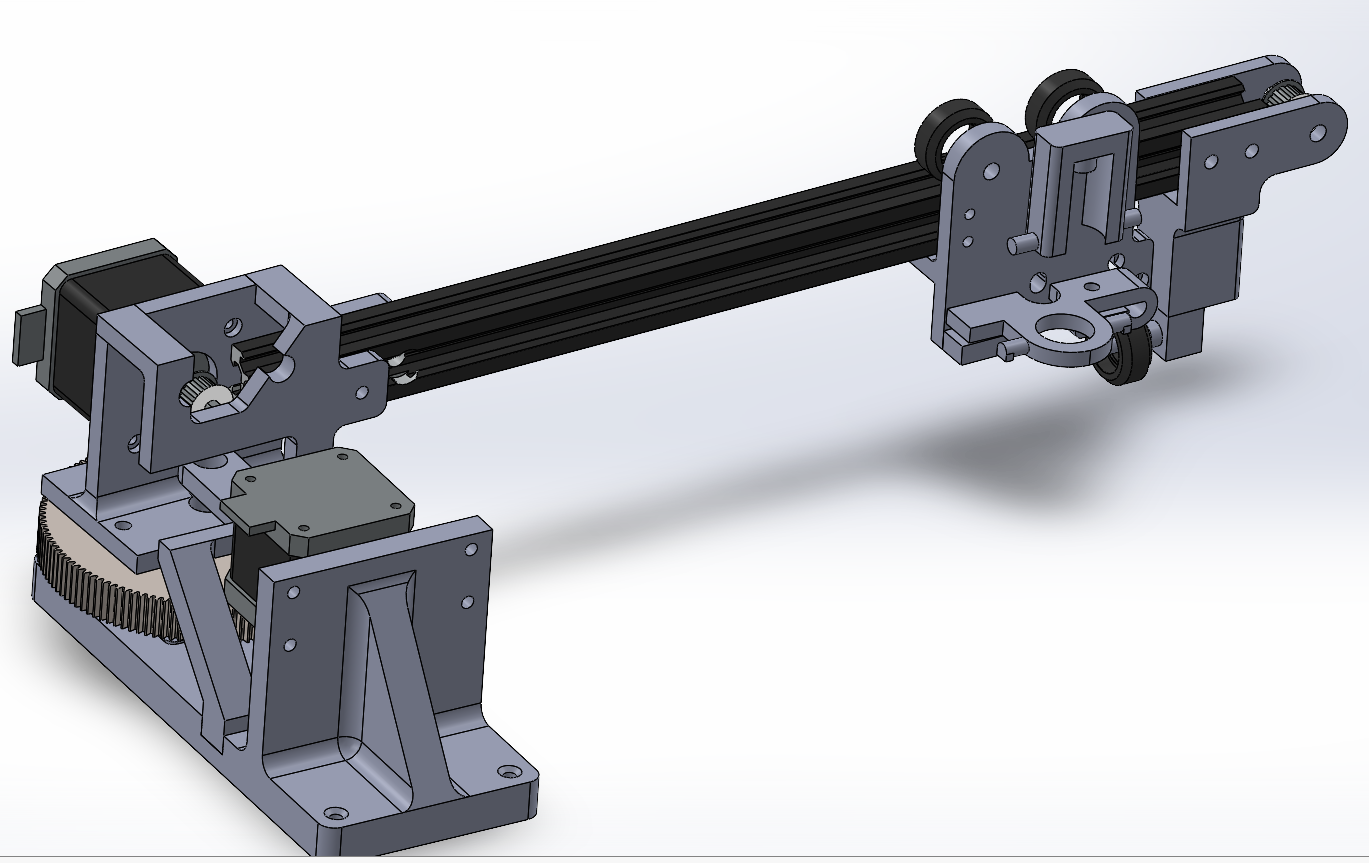
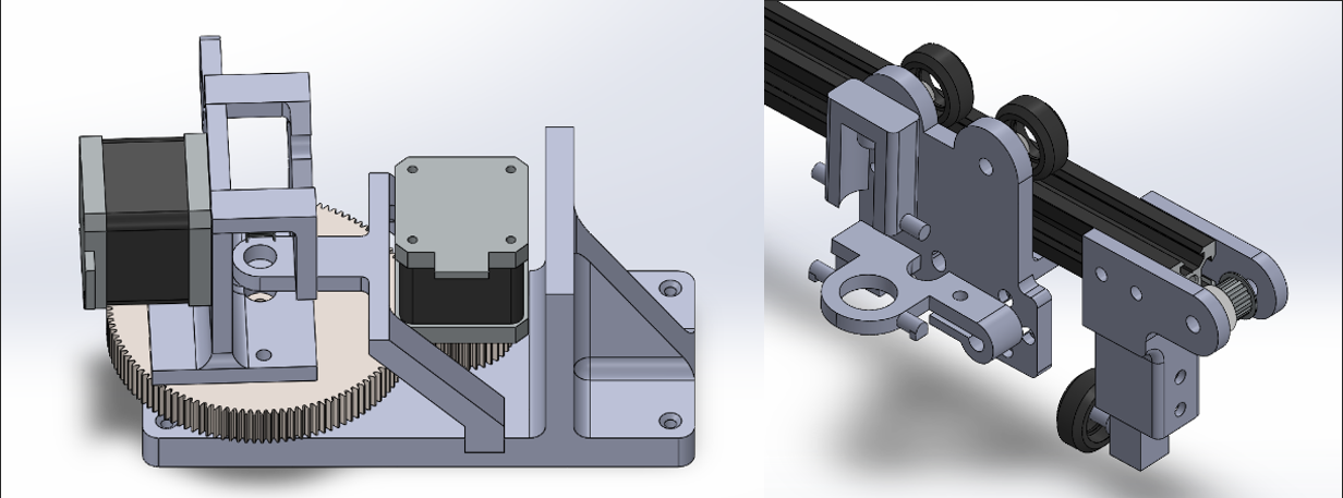
One of the NEMA 17 steppers mount on a 3D printed structure that is mounted on a white board and a piece of 3/4 plywood. This stepper is used to drvie the revolute motion of the plotter arm. The second stepper is used to drive the translation along the plotter's arm using a belt and pulley system. The pen and DC motor are mounted on the arm and translates when the belt is driven by the second stepper motor. The arm sits on a lazy susan bearing. A wheel is also connected to the end of the arm to provide additional support.
Stepper Drivers
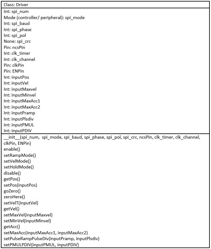
The TMC4210 driver class file is used to control the position or velocity of the steppers and can be used for different functions like, enable/disable, position/velocity reading, taget position/velocity setting, zeroing, and homing. The main routine uses a shceduler provided by the instructor of the class to run the tasks necessary to interpret an hpgl file stored in board memory and draw it on a white board. Inkscape was used to generate an hpgl file from desired image files. When the main routine is ran, the plotter waits for a button input to begin using the scheduler to parse the hpgl files for instructions and coordinates which are then sent to the steppers as integer theta inputs. The plotter then draws the image point by point until it finishes. Finally, when the drawing is finished the motors home to their original states. The driver class was designed accordingly to include those methods and the attributes necessary to implement those methods like several timer and pin objects.
Modeling
The kinematics modeling of the plotter was that of a 2DOF link that rotates about a fixed point. The end effector translates along the arm:
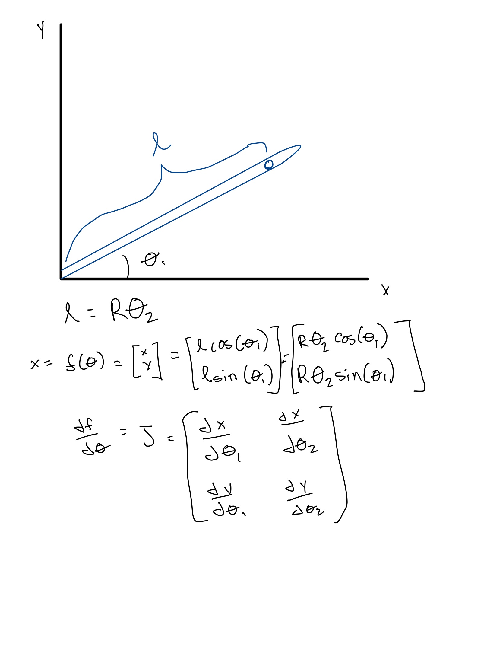
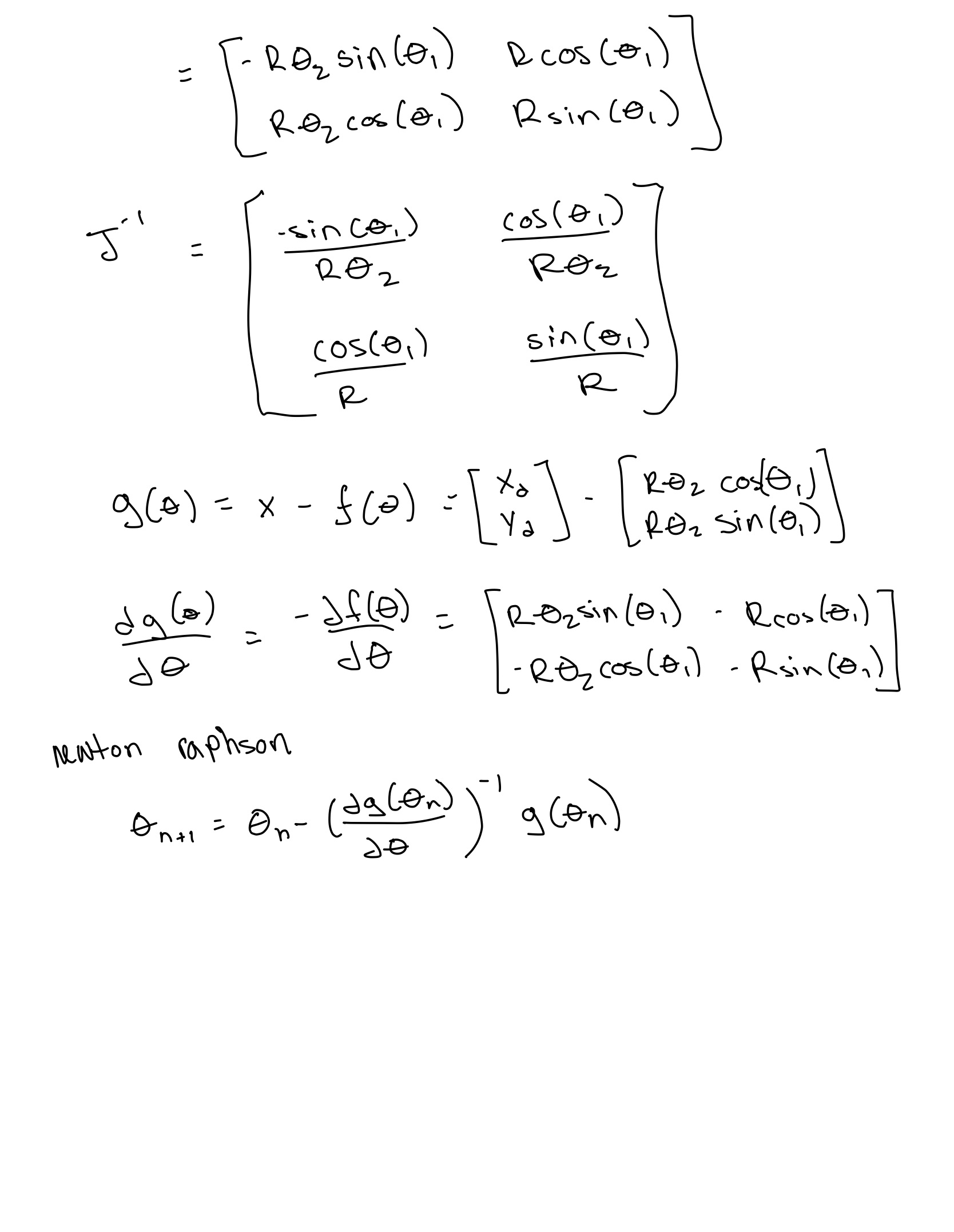
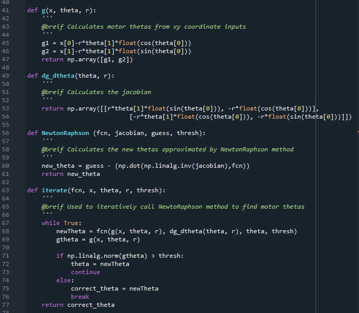
Using NewtonRaphson equation above, we set developed functions to iteratively solve for motor angles based on desired xy coordinates. Here is a code snippet of those fucntions:
Future Improvements
One unsolved issue so far has been the slight tilted outcome of the drawings. This was most likeley due to an improper conversion factor from the radius of the belt drive to distance draveled per rotation of the stepper on the robot arm. This inaccuracy caused the drawings to have streched coordintaes the farther the end effector traveled along the arm. Through more accurate measurements and calibration this issue might be solved although we didn't have enough time to.
- Date
- 06/09/2022